Basic testing/repair of vintage analogue LB/CB/dial phones
Contents
Contents
Circuits and parts
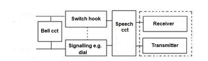
The following articles look at maintaining LB/CB/Dial 'phones. Most of the test and repair techniques are basically the same. The following block diagram explains the main parts of a typical analogue phone. You should be able to match each block with the relevant parts of each circuit below.
The following articles look at maintaining LB/CB/Dial 'phones. Most of the test and repair techniques are basically the same. The following block diagram explains the main parts of a typical analogue phone. You should be able to match each block with the relevant parts of each circuit below.
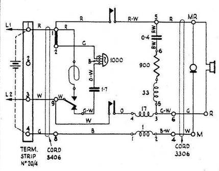
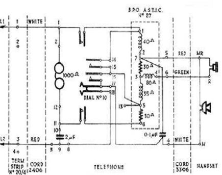
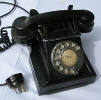
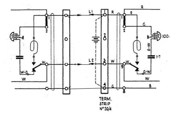
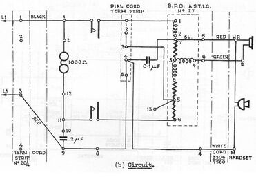
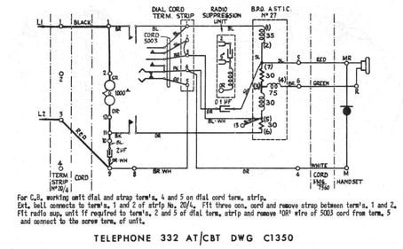
The following circuit diagrams are of UK designed Bakelite 300 series telephones used in Australia but the principles apply to most traditional analogue telephones. From L - R are shown Magneto, CB and Auto/Dial phones. It is interesting to note the differences in circuit symbols used in each of these drawings, in particular bells and microphones, even though they are all of the same generation of equipment. Image sources: various 1940-50s PMG documents.
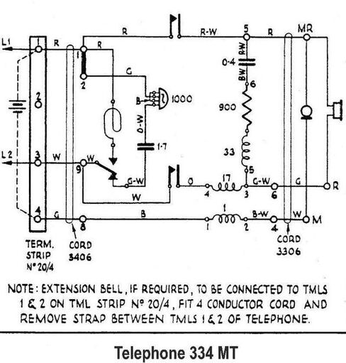
334 magneto telephone circuit
|

332 CB telephone.
|
332 dial telephone.
|
334 magneto. Image source http://www.telephonecollecting.org/Bobs%20phones/
|

332 CB. Image source: www.britishtelephones .com/t332.htm
|
332 Automatic. Image https://www.britishtelephones.com/aus/332type.htm
|
The first example above is a local battery - magneto telephone 334MT. Note the battery (usually located in a separate wall mounted box) is connected between terminals 1 and 4 on the external terminal strip (LH side of diagram). The battery voltage was typically 3 volts and its role was to power the transmitter (connected between terminals M and MR). The magneto generator is represented by the loop shaped symbol and changeover switch connected between terminals 1 and 9. Other components are similar to CB/dial 'phones, below. Although, curiously, the bell symbols are markedly different.
This website has kindly published an old PMG document on magneto telephone operation:
http://greypossom.com/data/Handbooks/Scanned_PDF/Magneto_Telephones.pdf
The second example is a 332 CB telephone. Note the absence of a local battery and generator and different type of ASTIC (anti-sidetone induction coil). The major parts of the circuit (from L-R) are; line connections L1 and L2, bell circuit (1000 ohm bell and capacitor), switch-hooks, dial terminal strip, ASTIC, handset cord and handset (receiver at top). there are no signalling components per se. The manual exchange detects line current when the handset is lifted and alerts the operator.
The final circuit is of a 332 automatic telephone. It is identical to the CB version but with the addition of a rotary dial in place of the straps on the dial cord term. strip. The circuit current paths of a 300 type phone can be viewed on the attached PDF document below.
Articles: 300/400 telephones
The following documents expand on 300 and 400 series telephones
(Note: These are internal documents on this page. Do not close them - simply click back to return to the page)
The following documents expand on 300 and 400 series telephones
(Note: These are internal documents on this page. Do not close them - simply click back to return to the page)
| 300_series_dial_telephone_diagrams_and_operation.pdf |
| comparison_300_400_auto_types.pdf |
| staa_300_and_400_series_magneto_telephones.pdf |
LB/magneto telephones
The last magneto telephone exchange closed in WA in 1985 so, at the time of writing (2020), there are still quite a few telephones around in private collections and for sale. Magneto telephones share similar operating principles to CB 'phones with the exceptions of magneto generator signalling and a local battery (usually 3V) to power the transmitter which, in turn, required a different ASTIC (voice coil).
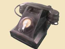
In early table mounted magneto telephones and also later Bakelite models, the local battery was usually contained in a skirting mounted, timber, metal or Bakelite box. In earlier, timber, wall models the battery was usually inside the main telephone. for example the 1920s Stromberg Carlson as shown below.
Magneto instruments can easily be set up as a simple point-to-point intercom system. Ref. circuit below, simply connect L1 and L2 to line and provide a small battery (1.5-3V) at each end. In the circuit below the battery connects at the terminal strip between terminals 1 & 4, and that's it. When signalling, remember to leave the handset on while ringing out, then pick up to listen and speak.
The last magneto telephone exchange closed in WA in 1985 so, at the time of writing (2020), there are still quite a few telephones around in private collections and for sale. Magneto telephones share similar operating principles to CB 'phones with the exceptions of magneto generator signalling and a local battery (usually 3V) to power the transmitter which, in turn, required a different ASTIC (voice coil).
In early table mounted magneto telephones and also later Bakelite models, the local battery was usually contained in a skirting mounted, timber, metal or Bakelite box. In earlier, timber, wall models the battery was usually inside the main telephone. for example the 1920s Stromberg Carlson as shown below.
Magneto instruments can easily be set up as a simple point-to-point intercom system. Ref. circuit below, simply connect L1 and L2 to line and provide a small battery (1.5-3V) at each end. In the circuit below the battery connects at the terminal strip between terminals 1 & 4, and that's it. When signalling, remember to leave the handset on while ringing out, then pick up to listen and speak.
Typical magneto telephone circuit
|

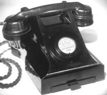
Typical 1950s 300 series magneto telephone. Has separate battery box
|
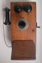
1920s Stromberg Carlson magneto telephone. Battery inside case
|
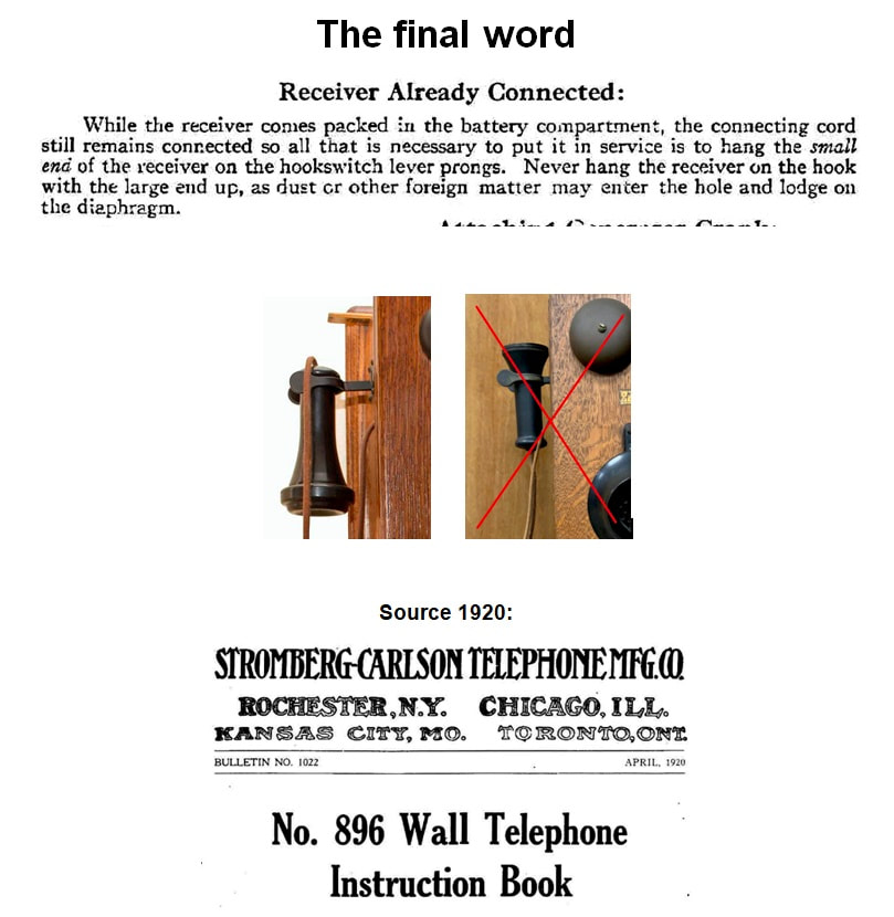
Early advice on hanging up bell style receivers.
Bells
There was a debate on one forum about whether the local bells should ring when ringing out with the magneto generator. It depends on the era and model. In the 334 example above, note the changeover switch on the generator. This automatically disconnects the bell set when the generator is turned. In some very early types the bell was permanently across the generator and rang each time but, as with the Commonwealth Ericsson, some models also provided a disconnect button.
3 wire magneto intercom or demo
To connect two instruments for demonstration purposes or very short distances (e.g. 50m) a single 1.5V cell and three wires will work. Connect L1 and L2 to each end, attach the battery at one end as discussed but run a third wire between terminals 4 (or equivalent) to power both ends. This is also the easiest way to test the operation of magneto telephones. Beware; there are several models of 300/400 series Bakelite magneto phones and in some cases the connections differ. In the example below, the battery connects between 1 and 8 on the phone's internal terminal strip but in a similar model they are 1 and 10. Double check the circuit!
Two magneto instruments set up as a 3 wire intercom
CB/dial telephones
The following are 332 type CB and dial telephone circuits and components. The dial version is the same as the CB with the dial connected to the dial cord terminal strip. This type’s operating principles are typical of most rotary dial phones from 1920s – 1980s. For example, 800 series models are described below under "Repairs" and they are not vastly different. On different models of phones the line connections, L1/L2, may be labelled as a/b, T/R etc.
The following are 332 type CB and dial telephone circuits and components. The dial version is the same as the CB with the dial connected to the dial cord terminal strip. This type’s operating principles are typical of most rotary dial phones from 1920s – 1980s. For example, 800 series models are described below under "Repairs" and they are not vastly different. On different models of phones the line connections, L1/L2, may be labelled as a/b, T/R etc.
332 CB telephone. Image source: http://www.telephonecollecting.org/
|
332 Auto telephone Source PMG handbook 1959
|
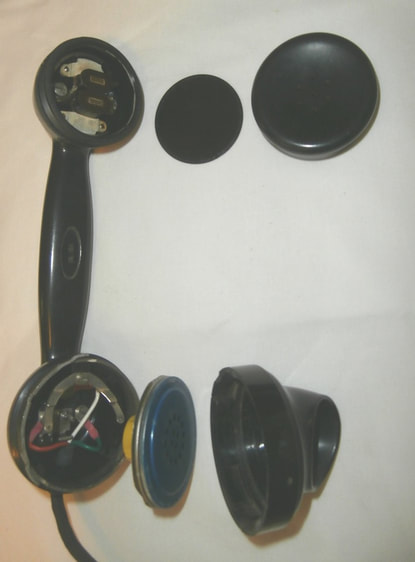
332 dial telephone -164 handset showing carbon transmitter/microphone capsule and electromagnetic receiver (diaphragm removed). Image source: J.Paskulich
Advice on dismantling 164 handset: https://antiquephones.blogspot.com/2008/
Receiver. Image source: http://telephonecollecting.org/receiveroperation.pdf
|
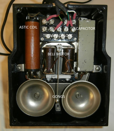
332 base showing ASTIC, capacitors, terminals and bell components. Image source; J. Paskulich
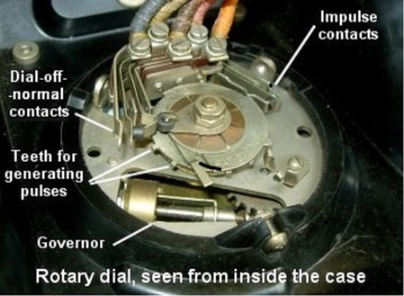
No. 10 "slipping cam" dial: Later superseded by No 12 etc. "trigger" dial. Image source; http://www.johnhearfield.com/Telephone/One_piece.htm
"Carbon transmitter/microphone" by wtshymanski http://en.wikipedia.org/wiki/Carbon_microphone#mediaviewer/File:
Carbon_microphone.svg
|

Repair
The majority of analogue dial telephones (and related CB and magneto models) are repairable. Although sometimes a bit "fiddly", many parts can be removed and replaced fairly easily with basic tools (screwdrivers, pliers etc). Some components may require soldering skills as well. There are quite a few sites on the internet with some good hints on repairs and maintenance. Although be a bit fussy, there are some rank amateurs out there too! Some examples of good quality sources:
http://www.samhallas.co.uk/telecomms.htm
https://antiquephones.blogspot.com/
https://www.ericofon.com/
Sam Hallas (UK) has produced some excellent descriptions on dismantling various types of antique and vintage telephones. Read these before launching blindly in to pulling something apart.
http://www.samhallas.co.uk/collection/bits_index.htm
Cosmetic repairs
Go to this page for some information on cosmetic repair/restoration of telephones. Also Arwin has some advice on repairing broken Bakelite. Always practice on low value items first! Go to:
http://www.matilo.eu/restauratie/hoe-repareer-ik-bakeliet-waar-een-chip-uit-is/?lang=en
Testing magneto telephones
Components can be tested similarly to CB/dial phones, as described below. The only exception is the generator. With a suitable meter connected to the line terminals, wind the handle briskly and it should produce >50V AC output. The basics of multimeters appear below. Another check is to apply a short circuit across the line terminals and again wind the handle. It should be difficult to turn as the load "brakes" the generator. Early magneto generators were meant to be regularly lubricated. Neglected ones are often difficult to turn. Drizzle small amounts of light oil onto all exposed rotating parts and into oiler tubes, if provided, and rotate gently. In most cases they will free up and work well.
Removing the "spitcup" style transmitter mouthpiece on 200 and 300 type telephones
These phones are fitted with 164 or 184 handsets (or variations thereof). The mouthpiece is held in place by a hidden spring bar. There is a small hole at the top of the mouthpiece. Insert a suitable tools such as a jewellers screwdriver or thin meter probe etc. and push firmly - at the same rotate the mouthpiece anti-clockwise. It should easily pop off. Refitting does not require the tool. Simply replace the mouthpiece and rotate clockwise until it clicks into place. An instruction appears at: https://www.youtube.com/watch?v=oiEt-ETrC28
Removing the transmitter and receiver caps on 400 and 800 series telephones
This also applies to the receiver cap on the earlier 164/184 handset. The caps simply unscrew anticlockwise but sometimes, after many years of neglect, they may be jammed on tight. BE GENTLE - don't try and force them off with multi-grip pliers or similar. Try drizzling some penetrant like WD40 around the screw thread and leave to soak in. After a while try and unscrew by hand with it wrapped in a PVC/rubber kitchen grip pad (the type used for taking lids off jars etc.). Alternatively, heat the cap gently with a hair dryer etc (it expands more than the handset body and should loosen) and try to unscrew as above. If the above fail, resort to the multi-grips wrapped in a grip pad after lubricating and/or heating.
UPDATE: 800 series telephone - basic repairs (added May 2019)
A short history of the 800 series telephones can be viewed here. Simply click on the PDF to open. It is within this site so simply click back to return to this page.
A short history of the 800 series telephones can be viewed here. Simply click on the PDF to open. It is within this site so simply click back to return to this page.
| 800_thg.pdf |
A detailed description of how 801/802 dial telephones work can be found on this page
Some simple videos of how to repair various components have kindly been published on youtube by vintagephones.com.au. These can be viewed at:
Replace line cord https://www.youtube.com/watch?v=T1Fki05y09U
Replace bell motor https://www.youtube.com/watch?v=-M6nDI7ojRc
Adjust bell ringer https://www.youtube.com/watch?v=1AH8x9-LM2Y
Replace dial cover https://www.youtube.com/watch?v=MCTA91eK6tA
Won't ring?
One issue that pops up regularly with these 800 series phones is that they won't ring.
If the bell coils are ok, the bell set armature operates freely and no other mechanical fault exists, the most likely problem is a missing strap on the circuit board. In early installations, there was a metal strap in the socket and the equivalent strap in the telephone wasn't connected. Refer to circuit here. If the phone was removed and re-installed elsewhere (no strap in socket) the strap needs to be connected inside the phone. Simply remove the case as described in the above videos and connect a wire strap (fitted with compatible press fit connectors) between terminals A and P1 on the circuit board. This simulates the strap in the early socket. In an original phone, it is possible that a spare wire strap is already waiting on terminal A.
NOTE: There may be slight variations between the terminal layout of early and late built 801/802 telephones. Check the circuit inside the case.
More details on testing and repairs follow.
Multimeters
A basic multimeter typically combines an ohmmeter, voltmeter and current meter (ammeter) in one package. Usually the function and range are selected with a rotary switch. The ohmmeter is probably the most useful function when testing an old telephone, out of circuit. In its simplest form, an ohmmeter is essentially a meter circuit and battery. It can supply a small current to the circuit under test and the current's magnitude indicates the circuit's continuity/resistance. Ideally the meter leads should have clips to give tight, reliable connections.
For novices, a very simple introductory video on multimeters can be viewed at:
https://www.youtube.com/watch?v=x7zOi1kJFk0. It is a good start. Beware, it is American and also shows someone poking the meter leads into their 120V AC power sockets etc. This is definitely NOT recommended with Australia's 230-240V system as our voltages can be fatal!
Testing continuity and resistance
Electrical "continuity" simply means that a circuit pathway is continuous i.e. complete, not broken. "Resistance", expressed in ohms (Ω), means that the circuit is still continuous but will oppose current flow by some amount. So continuity of a circuit path could range from 0Ω through to some much higher ohms value, depending on the components' functions. "Open circuit" means the circuit is broken and "short circuit" implies a, usually undesirable, zero (or low) ohms connection between two points in a circuit.
Ideally, components should be tested out of circuit otherwise other items connected across them can give false results. If a component cannot be tested out of circuit, make allowance in the measured value for other components that may be connected across it.
Never connect an ohmmeter to a live circuit as meter damage may result.
I prefer testing telephones with an old fashioned analogue meter as the needle deflection gives a more intuitive result.
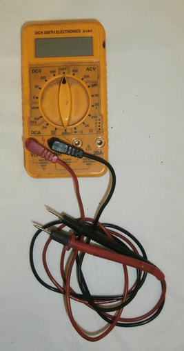
Typical digital multimeter. Image source: J. Paskulich
|
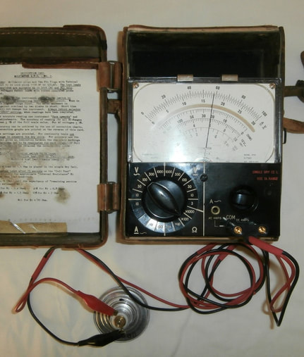
Analogue multimeter on ohms range testing a carbon transmitter's resistance. Image source: J. Paskulich
|
Continuity testing of telephone components
Wires and cords: With one lead of the ohmmeter on one end of a circuit pathway, continuity can be "chased" through circuit wiring.
Anti-sidetone Induction coil (ASTIC): Check the continuity/resistance of each winding. Results should be similar to stated ohms (Ω) values.
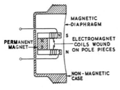
Receiver: Check the continuity of the coils. Also, by touching the meter lead on and off you should hear a crackle if it’s ok as the intermittent ohmmeter current varies the electromagnetic circuit thus moving the diaphragm. This effect is best observed with an analogue meter (electronic digital meters may not deliver enough current to drive the diaphragm).
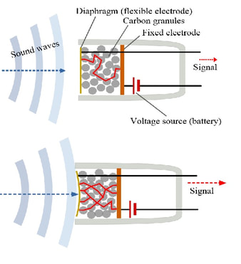
Carbon transmitter (AKA microphone): This is effectively a variable resistor comprising a diaphragm and container of carbon grains. Some ohms value will be noted but it should change if the unit is tapped or you blow on the diaphragm.
Capacitors: These appear to be open circuit but a good 1.5-2µF capacitor causes a small meter “kick” as the meter’s battery charges it up. This is best seen with an old fashioned analogue meter set on a high ohms range. Once charged the capacitor will appear as open circuit. To repeat the test simply reverse the meter leads' polarity.
Bell set: The bell motor coils should exhibit the stated ohms value.
Switch-hook contacts: You should see open circuit and closed (short) circuit appropriately when operated.
Dial contacts: Connect to the appropriate dial terminals, operate the dial and observe the pulsing and off-normal (ON) contacts’ making their open or short circuit connections during the dialling sequence. With an analogue ohmmeter you can get an idea of the dial’s pulsing performance by connecting across the pulsing contact terminals and dialling a number. For example, dialling 0 (ten pulses), the meter needle will "hover" at some mid range for the duration. Compare to known good dials to get an intuitive "feel" for what would be expected.
Note: I've recently come across a few dials where the pulsing or off-normal contacts are open circuit. Ensuring they close properly and a quick buff with coarse plain paper (or absolutely worst case, superfine -1200 grit - emery paper) has fixed the problem. Corrosion build up on the contacts is the cause. Have a look at my article on corrosion and contact whetting here on the ADSL page.
Wires and cords: With one lead of the ohmmeter on one end of a circuit pathway, continuity can be "chased" through circuit wiring.
Anti-sidetone Induction coil (ASTIC): Check the continuity/resistance of each winding. Results should be similar to stated ohms (Ω) values.
Receiver: Check the continuity of the coils. Also, by touching the meter lead on and off you should hear a crackle if it’s ok as the intermittent ohmmeter current varies the electromagnetic circuit thus moving the diaphragm. This effect is best observed with an analogue meter (electronic digital meters may not deliver enough current to drive the diaphragm).
Carbon transmitter (AKA microphone): This is effectively a variable resistor comprising a diaphragm and container of carbon grains. Some ohms value will be noted but it should change if the unit is tapped or you blow on the diaphragm.
Capacitors: These appear to be open circuit but a good 1.5-2µF capacitor causes a small meter “kick” as the meter’s battery charges it up. This is best seen with an old fashioned analogue meter set on a high ohms range. Once charged the capacitor will appear as open circuit. To repeat the test simply reverse the meter leads' polarity.
Bell set: The bell motor coils should exhibit the stated ohms value.
Switch-hook contacts: You should see open circuit and closed (short) circuit appropriately when operated.
Dial contacts: Connect to the appropriate dial terminals, operate the dial and observe the pulsing and off-normal (ON) contacts’ making their open or short circuit connections during the dialling sequence. With an analogue ohmmeter you can get an idea of the dial’s pulsing performance by connecting across the pulsing contact terminals and dialling a number. For example, dialling 0 (ten pulses), the meter needle will "hover" at some mid range for the duration. Compare to known good dials to get an intuitive "feel" for what would be expected.
Note: I've recently come across a few dials where the pulsing or off-normal contacts are open circuit. Ensuring they close properly and a quick buff with coarse plain paper (or absolutely worst case, superfine -1200 grit - emery paper) has fixed the problem. Corrosion build up on the contacts is the cause. Have a look at my article on corrosion and contact whetting here on the ADSL page.
Quick field tests of a rotary dial 'phone
(CB phone is the same minus the dial checks)
This is best done with an old fashioned analogue meter- for two reasons; first, the meter deflection is more intuitive than numbers varying on a display but, more importantly, digital meters have low ohmmeter currents and may not be sufficient to drive a 'phone receiver.
- Connect the ohmmeter between L1 and L2.
- On hook it should be open circuit but, on a high ohms range, you should see the slight kick of the bell circuit capacitor upon first contact. This implies that both the capacitor is OK and the bell coil windings are continuous.
- Off hook it will exhibit some ohms value (100-1000Ω) that varies if you tap or blow on the transmitter. Also you should hear the receiver crackle if the meter connections are moved. These checks show the transmitter and receiver are functional.
- Turn the dial off normal (O.N) and the meter should drop to low ohms. This checks the dial O.N. contacts are operating correctly, bypassing the speech paths in preparation for dial pulsing.
- Dial a number, e.g. 0, and observe the deflection of the meter. It should hold at some mid range of resistance on the meter while the dial is operating. This indicates the dial pulse contacts are functioning properly.
Generator test
If possible, obtain an old style magneto phone or generator and appropriate test leads. Connect to L1 and L2 of the phone under test. With this you can add to the above observations and check operation of the:
Bell: The phone’s bell should ring when the generator is operated implying a functional bell circuit.
Receiver: If you lift the handset, listen and wind the generator slowly at the same time, you should hear the generated signal which again proves the receiver path is ok.
Transmitter: If you wind the generator slowly, as above, and blow continuously into the transmitter, on each half cycle you may hear sidetone which suggests the transmitter and induction coil are working ok. NOTE: this test only applies to CB/dial and early push-button phones. In magneto instruments, the transmitter is separately powered. It can be checked by testing its resistance between the L1 and battery terminals as described previously.
Intuitive diagnostic aid to using the generator:
If the connection is open circuit the generator spins freely.
With a medium load (e.g. bells) some opposition to turning will occur.
With a heavy load (e.g. approaching a short circuit) the generator becomes difficult to turn.
Rotary dials
Telephone dials are robust but quite complex electro-mechanical devices. You will need appropriate skills and sophisticated testers to repair/adjust a dial to factory specifications, but the technical resources shown below may assist you in doing some general repairs on early British/Australian dials. My thanks to the authors for posting this information.
Some historical information on Australian dials and telephone numbers here
Sam Hallas in UK; A very interesting youtube video on how a typical ca. 1950 British (and thus Australian) telephone "trigger" dial works:
https://www.youtube.com/watch?v=ChbGQ-RyS80
Abdy Antiques in UK; An excellent video on dial impulse spring adjustment:
https://www.youtube.com/watch?v=XvgSJSLD30M
More tips at: https://antiquephones.blogspot.com/2008/12/fix-for-slow-dial-on-bakelite.html
Bob Freshwater UK: Detailed technical information on British (thus some early Australian) dials:
https://www.britishtelephones.com/dial1.htm
https://www.britishtelephones.com/dials/dialrep.html
The following is applicable to the no. 8 through to the no. 21 style dials used in Australian telephones from the 1920s to early 1960s. Th no. 8 and 10 were "slipping cam" types - described in Bob Freshwater's site above. An image also appears above under "CB/dial telephones". The no. 12 and no 21 types were "trigger" dials described in Sam Hallas' and Abdy Antiques videos above. Later dials used in the 800 series are not discussed here. I don't believe they were serviced in the field. Faulty units were replaced as a unit and returned to Workshops.
Just to confuse the novices. During the late 1950s through to 1960s(?), Australian PMG Workshops modified some no. 10 slipping cam dials to trigger operation with a local kit. These dials are easily recognised. The have the broad finger stop of the no. 10 on the front but a trigger mechanism on the rear. Also the pulse wheel teeth of the update kit are much deeper than in the no. 12.
Rough adjustment
Rotary dials are obsolete and will not signal over an NBN modem but some enthusiasts have found ways of interfacing them to the modem’s analogue, DTMF signalling, telephone port using “DialGizmo”, “Rotatone” devices etc. I haven’t tested these devices in depth but I suspect they will need the dial’s impulsing contact's make/break ratio and impulse speed to be very close to original specification. Also there cannot be any corrosion products or dirt on the impulsing and off-normal contacts (I have often found dials with open- circuit or high resistance contacts through dirt/corrosion - the phone cannot work).
The following are a few “bush mechanic” ideas and tips for servicing early British designed dials used in Australian 'phones until the 1960s. Again, you'll need the skills and proper test equipment to repair/adjust a dial to factory specifications but these hints may get an old dial to work well enough to get by.
1. The operating principles of rotary dials from the 1910s to end of production are basically the same.
2. Prior to any adjustments, ensure the dial is scrupulously clean. Use cotton buds, small brushes etc and then lightly oil moving parts and bearing surfaces. Ensure the governor moves freely and its weights and cup are clean. Do not flood the dial with WD40 or similar dispersal sprays (will eventually dry and "gum up").
3. Don’t fiddle with the coil return spring! If it’s broken or seized, it is beyond this discussion.
4. Watch the impulse spring set as you rotate the dial slowly and count the number of pulse operations for each number. 10 pulses for no. 0 through to one pulse for 1. Similarly, note the operation of the off-normal spring sets. As soon as the finger wheel is rotated slightly, they should close.
5. Make sure all the spring set contacts are clean, opening and closing properly and making good contact
(0 ohms). To clean (burnish), slide a piece of coarse paper (avoid emery paper if possible) between the
contacts - just enough to remove corrosion but not alter the contacts too much. See corrosion/contact
whetting here.
6. Check the dial impulsing speed. Australian dials should operate at 10 impulses/second. Dialling zero should take about 1.3 seconds (allows for an interdigital pause - note gap between the finger stop and first digit).
Speed is hard to get exactly without a dial tester but select zero and rotate to the stop - if it returns on the
count "one- one thousand and one", spoken normally - that is a rough estimation of 10 IPS.
Changing the speed is rarely necessary if the dial is undamaged, correctly lubricated and the governor is
clean and free running. You can change the speed by SLIGHTLY bending the governor arms EQUALLY in (faster) or out (slower).
7. The impulsing contacts make/break ratio cannot be determine without a proper dial tester. The best you can do is ensure the contacts are clean and correctly adjusted to 0.45 - 0.5 mm (for no. 12 dial) as described in Abdy Antiques’ video (above).
Arwin gives a good description on basic servicing of a European dial at:
http://www.matilo.eu/restauratie/hoe-reviseer-ik-eenvoudig-een-kiesschijf-draaischijf/?lang=en
An interesting discussion about servicing dials on a North American forum at:
http://www.classicrotaryphones.com/forum/index.php?topic=15120.0
Beware
Australian legislation requires that ALL telephones connected to the public switched telephone network are to be ACMA approved and nasty fines apply for breaches. Without reading all the bumf, I'm prepared to bet that privately imported foreign phones will NOT have approval. Similarly, some very old Australian telephones may not be compliant. These notes on testing telephone functionality do not imply, in any way, a recommendation to connect an unapproved phone to the Australian network.
Refer: http://www.acma.gov.au/Industry/Suppliers/Supplier-resources/Supplier-overview/compliance-marks.
