Telephone transmission systems
Contents
Contents
- 3 and 12 channel systems
- Broadband systems
To see an article on transmission systems in this author's home state of WA go here
Long distance telephony
Until the early part of the 20th century, the distance over which a (magneto) telephone could operate was limited to the size of its signalling generator, local battery voltage and the transmission loss of the line. Albeit, significant distances could be achieved. The trunk service between Melbourne and Sydney, a distance of around 1000 km, opened in 1907. https://trove.nla.gov.au/newspaper/article/198603490
The game changer was the development of the thermionic valve (AKA vacuum tube) during the first quarter of the 20th century. Valve amplifier repeaters were able to maintain satisfactory signal transmission over long distances. The first telephone call across the continent between Perth and Melbourne occurred on 18 Dec. 1930 - over an amplified VF circuit sharing the telegraph line.
https://trove.nla.gov.au/newspaper/article/33005893/2874475
A detailed description of the installation and operation of the above east-west system can be read on Sam Hallas' (UK) site. Go to pages 1-7:
http://www.samhallas.co.uk/repository/journals/POEEJ/POEEJ%20Vol%2025%20Pt%201%20April%201932.pdf
Only months earlier, the first international (radio) telephone call was made between Australia and Britain on 1 May 1930. https://trove.nla.gov.au/newspaper/article/73802363)
below some information on VF repeaters. It is assumed that the repeaters first installed were the "type 21". These used a clever design where a single vacuum tube amplifier served both directions of transmission. Problems were experienced with "singing" (unwanted feedback) and eventually they were made obsolete by the "type 22".
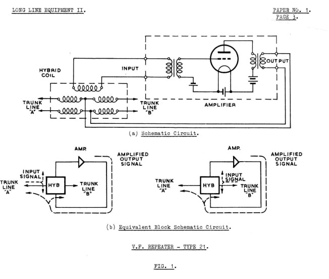
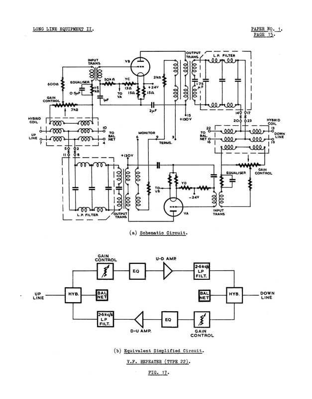
Later Type 22 VF Repeater.
|
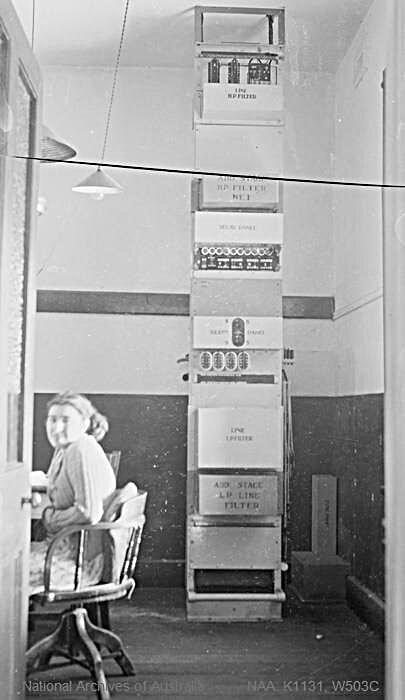
A typical repeater rack.- Carnarvon in the NW of WA 1939 (staff member unknown). Image source National Archives of Australia
|
Multiplexed Transmission Systems
Developed in the 1930s, analogue, frequency division multiplexed (FDM see below), 3 channel and 12 channel carrier systems operating over open wire pole routes were the first major "multiplexed" transmission systems in use across Australia. An interesting (US) tribute site to open wire telephone lines appears here.
Post WW2 Australia developed rapidly, demanding a similar development in telecommunications. From around 1960 the PMG embarked on an ambitious development programme and by the mid 1970s the majority of the country had a high capacity telephone transmission network, based mainly on FDM (see below) carried over coaxial cable and/or microwave radio systems. Coincident with the development of this national network was subscriber trunk dialling. In 1961-2 the only connections available were between Canberra and Sydney and from Warragul (Vic.) to Melbourne. By 1975 over 90% of Australian subscribers had access to STD (source: ABS Official Yearbook of Australia no. 61 1975).
Until the start of the 21st C. the major role of the various transmission systems used in Australia was to provide multiple telephony paths. Even optical fibre based, digital systems of the time were structured for telephony multiplexers. It was not until the start of the 21st C., and the rise of the internet, that their purpose shifted to providing high speed customer end-to-end digital services.
Frequency division multiplexing (FDM)
"Multiplexing" combines and transmits a number of separate signals over one path. For example, very early 3 channel, open wire systems took three telephone circuits and, using electronic principles, altered their frequency ranges so that they each occupied their own individual frequency band above the existing voice band. In this way a maximum of four simultaneous telephone conversations could be sent over a line that previously could only transmit one conversation. This significantly improved efficiency and reduced costs.
FDM is a principle developed in the early 20th century alongside the development of vacuum tube electronics. Analogue signals, usually telephone speech circuits - "channels" (although the principle was applied to other signals such as telegraphy as well) were progressively "modulated" with "carrier frequencies" to higher and higher frequency bands. At the receive end, the channels were "demodulated" back to their original speech frequencies. The term "modem" is well known. it is a portmanteau word from modulator/demodulator and originated with carrier telephone technology.
Channels were combined into blocks of frequencies depending on the capacity of the transmission equipment and transmitted over a range of transmission lines/systems including open wire pole routes, underground coaxial cables or microwave radio systems.
3 and 12 channel systems
Very early systems were typically 3 (speech) channel systems operating over open wire pole routes. They occupied frequencies up to about 30 kHz. These were followed by 12 channel systems which operated above the 3 channel systems in the range of about 36 - 140 kHz. By the mid 20th c. much higher frequency (and channel capacity) systems had been developed. A (USA but similar to Australian) technical summary of early 3 channel and 12 channel systems operation over open wire lines can be found online at:
http://www.vias.org/albert_ecomm/aec11_telephone_toll_service_031.html
The first 12 channel system in Australia was installed between Melbourne and Sydney at the end of 1938.
Analogue broadband systems
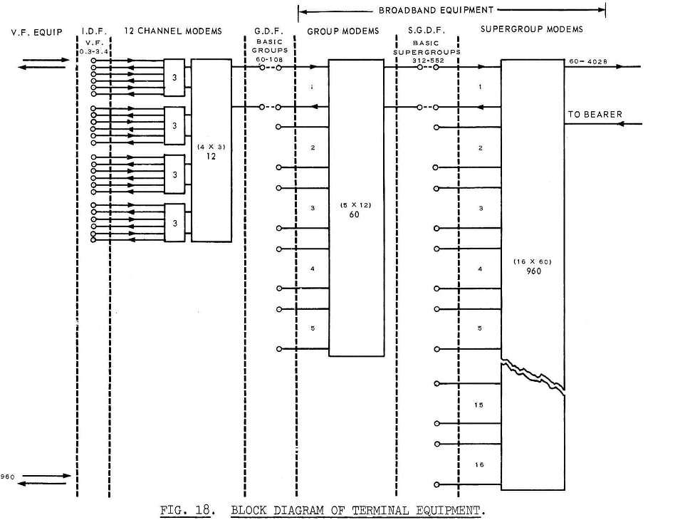
The basic unit was the telephone channel comprising a frequency band of 0 - 4kHz which was sufficient to pass intelligible speech (0.3 - 3.4kHz) plus signalling paths for call set-up. In analogue broadband systems, these channels were "stacked" in progressively higher frequency bands using frequency division multiplexing (FDM) into "groups" of 12 channels, 'supergroups' of 60 channels, 'mastergroups' of 300 channels etc. into a high frequency band compatible with the available transmission media - coaxial cable, microwave radio systems etc.
The following block diagram of FDM 960 channel terminal equipment was extracted from Australian Post Office training document CP225 (1968) page 8 "Broadband Terminal Equipment". This and many other documents are available to members on the STAA website https://telecommunicationsandsound.com/ - click on "membership details" to find a club in your area.
"Multiplexing" combines and transmits a number of separate signals over one path. For example, very early 3 channel, open wire systems took three telephone circuits and, using electronic principles, altered their frequency ranges so that they each occupied their own individual frequency band above the existing voice band. In this way a maximum of four simultaneous telephone conversations could be sent over a line that previously could only transmit one conversation. This significantly improved efficiency and reduced costs.
FDM is a principle developed in the early 20th century alongside the development of vacuum tube electronics. Analogue signals, usually telephone speech circuits - "channels" (although the principle was applied to other signals such as telegraphy as well) were progressively "modulated" with "carrier frequencies" to higher and higher frequency bands. At the receive end, the channels were "demodulated" back to their original speech frequencies. The term "modem" is well known. it is a portmanteau word from modulator/demodulator and originated with carrier telephone technology.
Channels were combined into blocks of frequencies depending on the capacity of the transmission equipment and transmitted over a range of transmission lines/systems including open wire pole routes, underground coaxial cables or microwave radio systems.
3 and 12 channel systems
Very early systems were typically 3 (speech) channel systems operating over open wire pole routes. They occupied frequencies up to about 30 kHz. These were followed by 12 channel systems which operated above the 3 channel systems in the range of about 36 - 140 kHz. By the mid 20th c. much higher frequency (and channel capacity) systems had been developed. A (USA but similar to Australian) technical summary of early 3 channel and 12 channel systems operation over open wire lines can be found online at:
http://www.vias.org/albert_ecomm/aec11_telephone_toll_service_031.html
The first 12 channel system in Australia was installed between Melbourne and Sydney at the end of 1938.
Analogue broadband systems
The basic unit was the telephone channel comprising a frequency band of 0 - 4kHz which was sufficient to pass intelligible speech (0.3 - 3.4kHz) plus signalling paths for call set-up. In analogue broadband systems, these channels were "stacked" in progressively higher frequency bands using frequency division multiplexing (FDM) into "groups" of 12 channels, 'supergroups' of 60 channels, 'mastergroups' of 300 channels etc. into a high frequency band compatible with the available transmission media - coaxial cable, microwave radio systems etc.
The following block diagram of FDM 960 channel terminal equipment was extracted from Australian Post Office training document CP225 (1968) page 8 "Broadband Terminal Equipment". This and many other documents are available to members on the STAA website https://telecommunicationsandsound.com/ - click on "membership details" to find a club in your area.
Analogue transmission systems in Australia were gone by the turn of the 21st century. This website gives an idea of the FDM process. Australia used the CCITT scheme.
https://en.wikibooks.org/wiki/Communication_Systems/Frequency-Division_Multiplexing
https://en.wikibooks.org/wiki/Communication_Systems/Frequency-Division_Multiplexing
Coaxial cable
Further information on the operation of coaxial cable broadband systems installed in WA can be seen here
A coax. cable "pair" consists of two electrical conductors arranged such that one wire is located inside another which is in the form of a tube. The conductors are separated by suitable insulation. Although now mostly obsolete in underground telecommunications cabling systems, the coax. principle is still used extensively in "internal" high speed/high frequency transmission equipment cables. The layout of the conductors naturally shields its signals from external electromagnetic radiation and similarly minimises radiation of the transmitted signals. This results in good signal to noise ratios, relatively low loss and enables wide-band frequency transmission. Modern "internal" coaxial cables use solid polyethylene (or similar) insulation but the underground cable tubes were "air cored" employing insulating spacers rather than solid core. This improved their transmission properties.
The typical coax cable used in the PMG systems of the 1960-70s comprised a lead sheath, several pairs of coax. tubes plus additional bundles of traditional "interstitial" cable pairs in between the tubes. The interstice pairs provided control and local telephone circuits and the coax tubes provided high frequency transmission paths for FDM telephony and television. Telephony required two tubes per system (both-way transmission). Unidirectional TV only required one tube but the second was usually kept as standby.
The following image of a piece of coax from that time was taken from Colin McDiarmid's Flickr post which can be viewed at:
https://www.flickr.com/photos/151495594@N04/albums/72157680514592172/page6
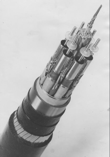
Piece of coaxial cable showing coaxial tubes and bundles of interstice pairs. Image source: Colin McDiarmid.
Melbourne-Sydney Coaxial Cable Project
A series of detailed articles and images on the first Melbourne - Sydney coaxial cable project in the early 1960s can be found in The TELECOMMUNICATION JOURNAL of Australia VOL. 13, No. 3 FEBRUARY, 1962 -Special issue Sydney-Melbourne Coaxial cable project here
A series of detailed articles and images on the first Melbourne - Sydney coaxial cable project in the early 1960s can be found in The TELECOMMUNICATION JOURNAL of Australia VOL. 13, No. 3 FEBRUARY, 1962 -Special issue Sydney-Melbourne Coaxial cable project here
Microwave radio systems network
Coincident with the development and installation of coaxial cable networks in Australia in the 1960s-70s were the microwave radio systems installed for the expanding PMG (analogue) broadband network. The original systems in WA were provided by GEC UK. I believe later updates were sourced from NEC Japan. The following information was derived from various publicity releases from GEC at the time. My thanks to Mr A. Hampel for providing the source material.
Coincident with the development and installation of coaxial cable networks in Australia in the 1960s-70s were the microwave radio systems installed for the expanding PMG (analogue) broadband network. The original systems in WA were provided by GEC UK. I believe later updates were sourced from NEC Japan. The following information was derived from various publicity releases from GEC at the time. My thanks to Mr A. Hampel for providing the source material.
GEC microwave transmission systems in Australia 1962
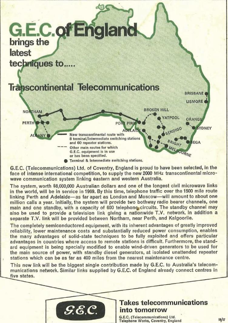
The following text and images are derived from an advertisement placed by GEC (UK) in the “Post Office Electrical Engineer’s Journal” (the British equivalent of our Telecom Journal of Australia) October 1962. It gives a general outline of existing and proposed microwave radio systems in Australia at the time.
“The GEC is to supply microwave equipment to the APO for four new SHF radio-relay systems. The equipment is suitable for the transmission of either television and its associated sound programme signals or 960 telephone circuits. Each system can be easily extended to provide one standby radio channel for a group of up to three working radio channels for any one direction of transmission.
Each radio frequency channel operates in the frequency band between 5925Mc/s and 5425Mc/s and is similar to that which is already operating in routes between Sydney and Orange and between Brisbane and Lismore (Mt Mardi)
The four new systems are as follows:
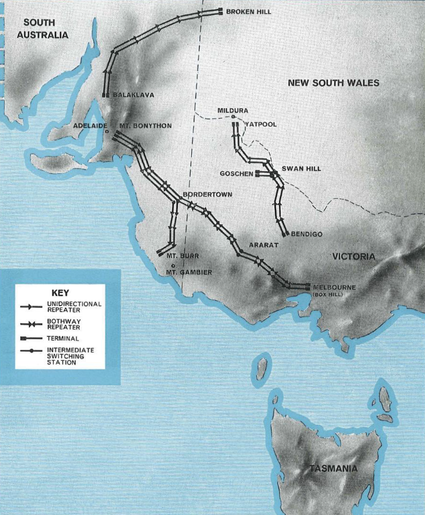
Adelaide – Mt Gambier – Melbourne
The equipment for this system is arranged initially to relay (a) television plus sound programme signals from Adelaide (Mt Bonython) to Mt Gambier (Mt Burr) and (b) telephone circuits between Adelaide and Melbourne (Box Hill). The system includes seventeen hops with intermediate switching stations at Bordertown and Ararat.
Balaklava – Broken Hill
The equipment for this system is arranged initially to relay (a) television plus sound programme signals from Balaklave to Broken Hill. The system includes seven hops.
Bendigo – Swan Hill – Mildura
The equipment for this system is arranged initially to relay (a) television plus sound programme signals from Bendigo to Swan Hill (Goschen) and Mildura (Yatpool). The system includes ten hops with an intermediate switching station at Swan Hill.
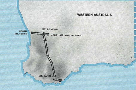
Perth – Northam – Albany
The equipment for this system is arranged initially to relay (a) television plus sound programme signals from Perth to Northam (Needling Hills) and Albany (Mt Barker). The system includes nine hops with intermediate switching stations at Mt Bakewell.”
The following text and images are derived from an advertisement placed by GEC (UK) in the “Post Office Electrical Engineer’s Journal” (the British equivalent of our Telecom Journal of Australia) October 1962. It gives a general outline of existing and proposed microwave radio systems in Australia at the time.
“The GEC is to supply microwave equipment to the APO for four new SHF radio-relay systems. The equipment is suitable for the transmission of either television and its associated sound programme signals or 960 telephone circuits. Each system can be easily extended to provide one standby radio channel for a group of up to three working radio channels for any one direction of transmission.
Each radio frequency channel operates in the frequency band between 5925Mc/s and 5425Mc/s and is similar to that which is already operating in routes between Sydney and Orange and between Brisbane and Lismore (Mt Mardi)
The four new systems are as follows:
Adelaide – Mt Gambier – Melbourne
The equipment for this system is arranged initially to relay (a) television plus sound programme signals from Adelaide (Mt Bonython) to Mt Gambier (Mt Burr) and (b) telephone circuits between Adelaide and Melbourne (Box Hill). The system includes seventeen hops with intermediate switching stations at Bordertown and Ararat.
Balaklava – Broken Hill
The equipment for this system is arranged initially to relay (a) television plus sound programme signals from Balaklave to Broken Hill. The system includes seven hops.
Bendigo – Swan Hill – Mildura
The equipment for this system is arranged initially to relay (a) television plus sound programme signals from Bendigo to Swan Hill (Goschen) and Mildura (Yatpool). The system includes ten hops with an intermediate switching station at Swan Hill.
Perth – Northam – Albany
The equipment for this system is arranged initially to relay (a) television plus sound programme signals from Perth to Northam (Needling Hills) and Albany (Mt Barker). The system includes nine hops with intermediate switching stations at Mt Bakewell.”
|
|
The east-west network
The east-west system opened in July 1970. A detailed group of articles about this system can be read in the Telecommunications Journal of Australia February 1971 (Vol 21 No. 1) available at: http://www.coxhill.com/trlhistory/history/australian_publications.htm
The east-west system opened in July 1970. A detailed group of articles about this system can be read in the Telecommunications Journal of Australia February 1971 (Vol 21 No. 1) available at: http://www.coxhill.com/trlhistory/history/australian_publications.htm
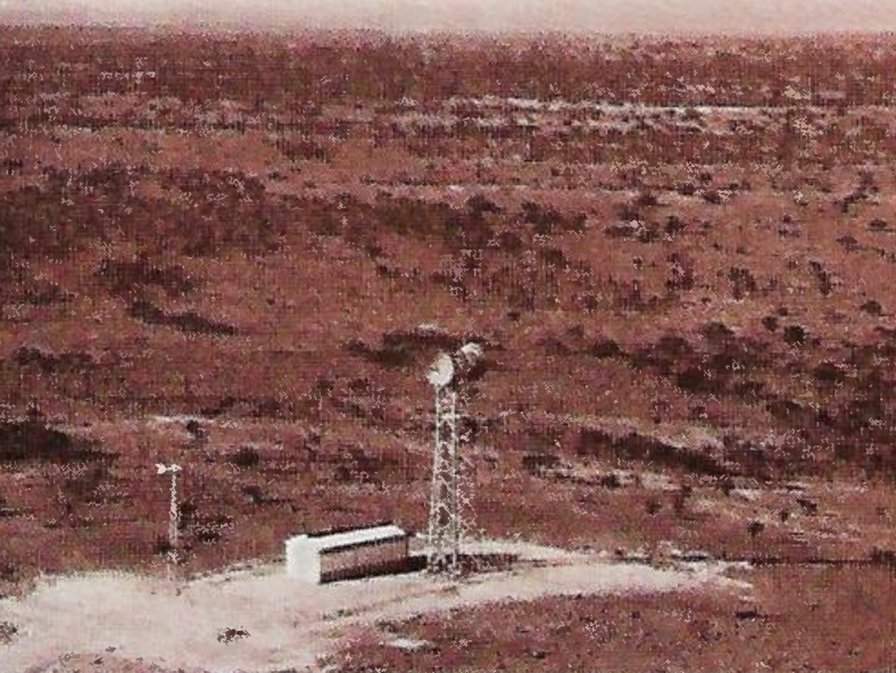
East-west microwave repeater site ca. 1970. L-R wind generator, equipment hut and tower and dishes. Image source Telecommunications Journal of Australia February 1971
Source: Advert. UK Post Office Telecommunications Journal Autumn 1967
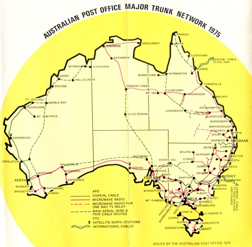
The Australian Transmission Network 1974
The "National Broadband Network" was a 1970s Telecom Australia description of the analogue "trunk" transmission systems network that covered Australia. The term has been appropriated in recent years to mean the digital customer access network - NBN.
I found the following diagram showing the national network in a 1975 Telecom Australia publicity brochure.
To put it into context, Australia has an area of 7 689 000 square km, a coastline of approx. 20 000 km, is approx. 4000 km est to west and 3200 km north to south. In 1975 the Australian population was a little under 14 million. Today (2021) the network is wholly digital transmission systems and the population is around 26 million.
Australian Transmission Network 1980s
The following PDF documents are from Telecom Australia publicity dept from around the mid 1980s. Simply click once to open and back to return to the page
The following PDF documents are from Telecom Australia publicity dept from around the mid 1980s. Simply click once to open and back to return to the page
| linking_a_nation.pdf |
| satellites_the_vital_connection.pdf |
Time division multiplexing
From about 1980 there was a shift towards digital multiplexing technology and digital transmission systems (e.g. optical fibre) in Australia. The first east-west optical fibre opened in 1989.
Time division multiplexing TDM is a means of combining many low-speed digital signals into a single high-speed pulse train. A detailed article on TDM principles can be viewed at the "ScienceDirect" site here. It mainly refers to the USA 24 channel version but principles are the same as the Australian 30 channel systems.
In Australian and European telephony, the basic building block was the 30 channel PCM multiplexer. 30 analogue telephone channels (as above 0-4 kHz) were first converted to digital signals ( 0s and 1s) using pulse code modulation (PCM). A detailed article on PCM concepts can be seen at the "ElProCus" site here.
These PCM encoded channels are then "stacked" in time slots by time division multiplexing (TDM) into a nominal 2Mb/s data stream. These 2Mb/s streams, in turn, could be combined in higher order multiplexers to suit the capacity of the transmission medium e.g. optical fibre systems.
Some background on contemporary (plesiochronous) digital multiplexing (PDH) concepts is provided by "Carritech Telecommunications" and can be viewed here. Since the 1990s, PDH has been superseded by the synchronous digital hierarchy (SDH). SDH is beyond the scope of this discussion but a definition and brief overview by "NFON" appears here.
Digital Radio Concentrator System (DRCS)
The Digital Radio Concentrator System (DRCS) was deployed by Telecom Australia during the 1980s to provide automatic telephone services to customers in outback Australia. Prior to DRCS, these rural customers were connected to local manual exchanges or, if particularly remote, had to rely on the vagaries of high frequency two-way radio.
A detailed article, prepared for the Telecommunications Association (TelSoc), on DRCS can be found on-line at:
https://telsoc.org/sites/default/files/journal_article/242-article_text-2447-1-11-20200213v2.pdf
Australian Optical Fibre Network 1985 - 2000
Optical fibre transmission systems are ideally suited to digital multiplexing systems and became the norm in Australia after the 1980s. Basic optical fibre principles can be viewed here.
The image below gives a concept map of the Australian network from 1985. I had some experience in the late 1980s - early 90s with 140Mbs OF systems in WA and was across the first e-w project. (Perth - Adelaide single-mode 565Mbs system completed late 1989) but the memory's faded, I left my records behind when I left Telecom and there is very little historical information on-line. If former Telecom Australia staff have any images, approximate dates or general information I'd be pleased to hear from you. Contact me here.
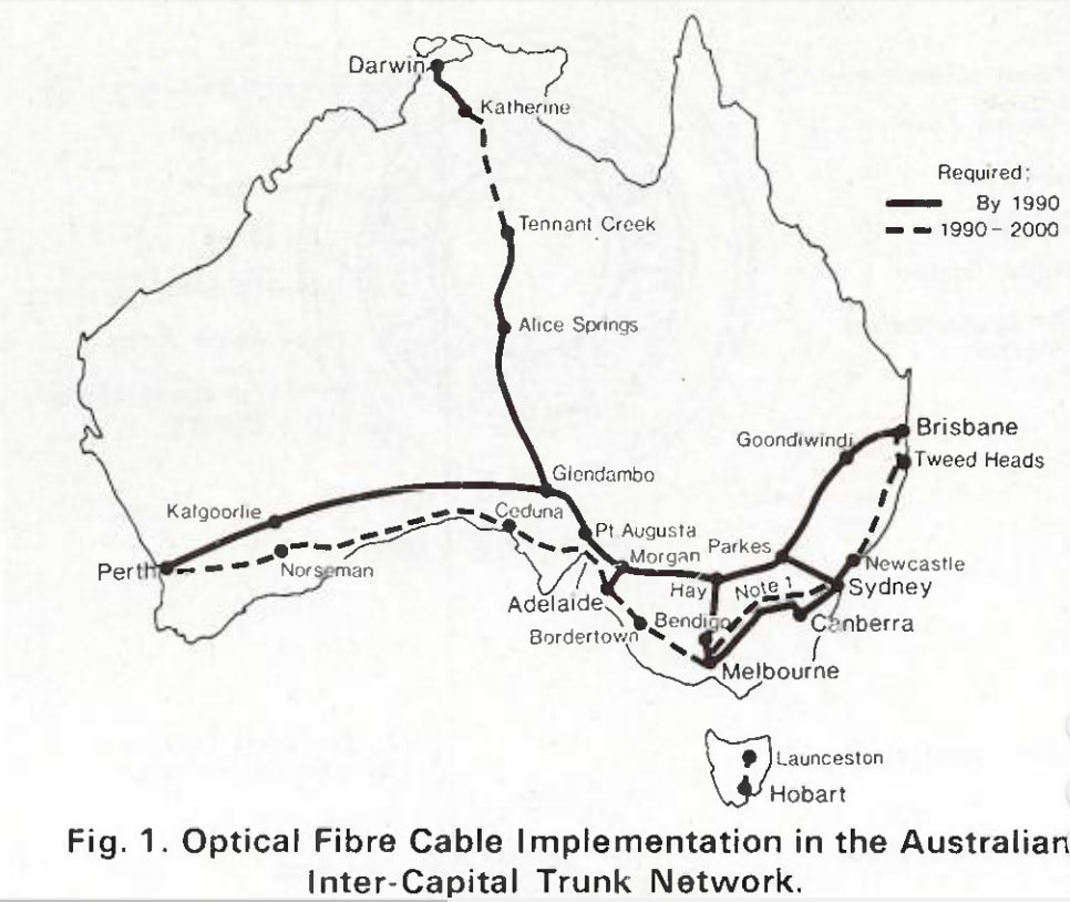
Image source: Cable Design and Installation Technique for Direct Buried Non-Metallic Optical Cables. B. T. deBoer, R. W. A. Ayre, R. B. Schuster. Telecommunications Journal of Australia Volume 35 No. 3 1985.
NBN (Digital National Broadband Network) 2009 -
No discussion on the history of Australian telecommunications transmission systems would be complete without mentioning the National Broadband Network (NBN). Implemented by the Kevin Rudd Labor Government a couple of years after its election in 2007, the NBN was to connect the majority of Australian premises directly to an integrated digital communications system over a high speed optical fibre network. It was a heroic project predicted to cost many tens of billions of dollars and take a couple of decades to complete. The (Liberal) conservative government (2013 -), initially led by Tony Abbott, has reviewed this project and looked at ways to reduce the costs, so the performance outcomes may not be as originally expected. Whatever happens, the NBN has ultimately spelt the end of the public switched telephone network and analogue telecommunications. More information on analogue and digital telephony can be found here and on the NBN here.
The following NBN network map is not up-to-date but it shows an overview of the major telecommunications transmission paths in the second decade of the 2000s. The network has been upgraded wholly to digital transmission systems (mostly optical fibre) but its extent closely follows that installed 40 years prior. A 2016 map of WA showing all major infrastructure systems, including Telstra's intrastate and international optic fibre network connections (yellow), can be viewed here
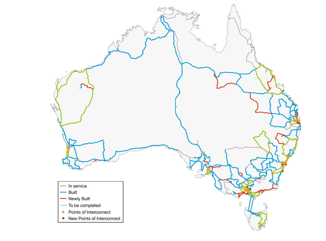
Image source: https://blog.jxeeno.com/nbn-co-reveals-18-month-rollout-plan/
